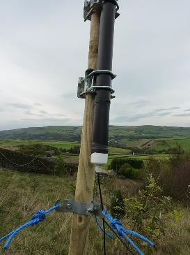
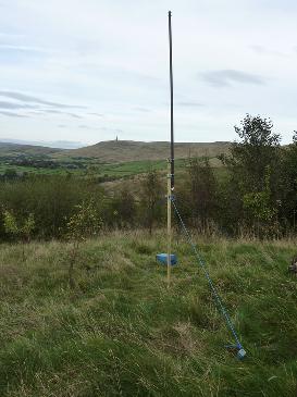
 This is a 2.8m monopole electrode clamped to the top of a wooden
post as in the adjacent photos. The pole is held upright by three ropes.
This is a 2.8m monopole electrode clamped to the top of a wooden
post as in the adjacent photos. The pole is held upright by three ropes.
This is a 2.8m monopole electrode clamped to the top of a wooden
post as in the adjacent photos. The pole is held upright by three ropes.
The guy ropes are modelled as three separate wire electrodes so that they are brought out to separate terminals in the Spice model. In dry weather they are practically insulators and have no effect on the antenna but when soaked they act as grounded wires.
Similarly the wooden support post becomes a conductor when wet, so this is represented in the model by a cylinder electrode.
We want to calculate the effective height and corner frequency of the
antenna when connected to a preamp with 100M input resistance.
The input file monopole.in is listed below. Note the use of trig functions to position the guy wires at 120 degree intervals around the post.
   electrode {

      name antenna

      cyl {
         end1 0.08, 0, 2.2
         axis 0,0
         length 2.8
         radius 22e-3/2
         tiles 2000
      }
   }

   electrode {

      name ground

      disc {
         center 0,0,0
         radius 10
         axis 0,0
         tiles 6000
      }
   }

   electrode {

      name support_post

      cyl {
         end1 0,0,0
         axis 0,0
         length 2.4
         radius 50e-3/2
         tiles 3000
      }
   }

   electrode {
      name guy_0

      wire {
         end1 0, 0, 1.8
         end2 0, 2.5, 0
         wirad 3mm
      }
   }

   electrode {
      name guy_120

      wire {
         end1 0, 0, 1.8
         end2 2.5 * sin(120 * pi/180), 2.5 * cos(120 * pi/180), 0
         wirad 3mm
      }
   }

   electrode {
      name guy_240

      wire {
         end1 0, 0, 1.8
         end2 2.5 * sin(240 * pi/180), 2.5 * cos(240 * pi/180), 0
         wirad 3mm
      }
   }

   field {
      electric 0,0    ; Vertical field
   }
Generate a Spice sub-circuit with
lcng -o spice monopoleThe layout expands to about 12,000 tiles so takes a few minutes to run.
The comments embedded in the sub-circuit indicate which 'pins' belong to which electrode:
   .SUBCKT monopole INF E6 E5 E4 E3 E2 E1 EF
   *
   * pin 1: zero of potential at infinity
   * pin 2: GUY_240
   * pin 3: GUY_120
   * pin 4: GUY_0
   * pin 5: SUPPORT_POST
   * pin 6: GROUND
   * pin 7: ANTENNA
   * pin 8: E-field, 1 volt = 1 volt/metre
   *
   ...
A test circuit is shown below. An AC signal of 1V is applied to pin 8 to create a 1V/m vertical E-field. The wet guy ropes will have some resistance, we'll represent that with a 10k resistance from each guy to ground. Likewise, for the support post. The file monopole-test.spice contains
   Monopole
   .AC DEC 10 1 100K
   .PRINT AC V(5)

   .INCLUDE monopole.spice

   * 1 volt AC to create the incident E-field
   Vin 0 6 DC 0 AC 1.0

   X1 0 1 2 3 4 0 5 6 monopole

   * Post and guy resistances
   RG240 1 0 10K
   RG120 2 0 10K
   RG0 3 0 10K
   RP 4 0 10K

   * Front end bias resistor
   RB 5 0 100e6
   .END
Running this model produces the 'Wet antenna' response below
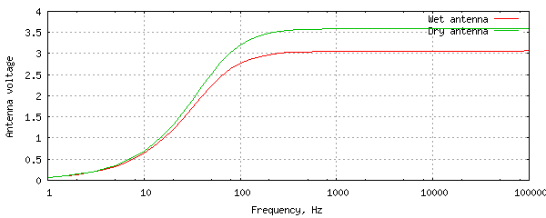
The corner frequency is about the same (50Hz) for wet and dry conditions, but the antenna effective height is affected. The antenna voltage above the corner frequency is 3.6V when dry and about 3.1V when wet. The incident field is 1V/m therefore these voltages directly give the effective antenna height.
These models are very approximate because we have guessed values of the wet pole and guy resistances. However it demonstrates that they have an effect and suggests it is desirable to use metal guy wires and support post, with the small cost of some effective height, so that the calibration of the antenna does not vary with the weather.